CSM Acoustic Insulation · Sound insulation, lab-validated
Professional sound-insulation calculation — airborne and impact.
Design layer by layer or with AI help, compare solutions on a single chart and document the performance — with open empirical validation against laboratory measurements. For partitions, façades, floors, ceilings and separating elements.
Validated vs lab · ISO 717 · ASTM E413 · ISO 12354 · 10 languages
Download

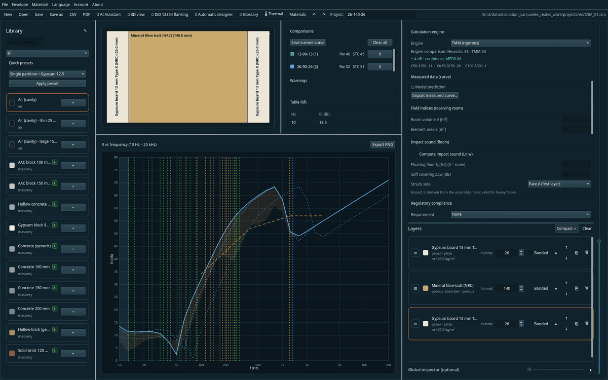
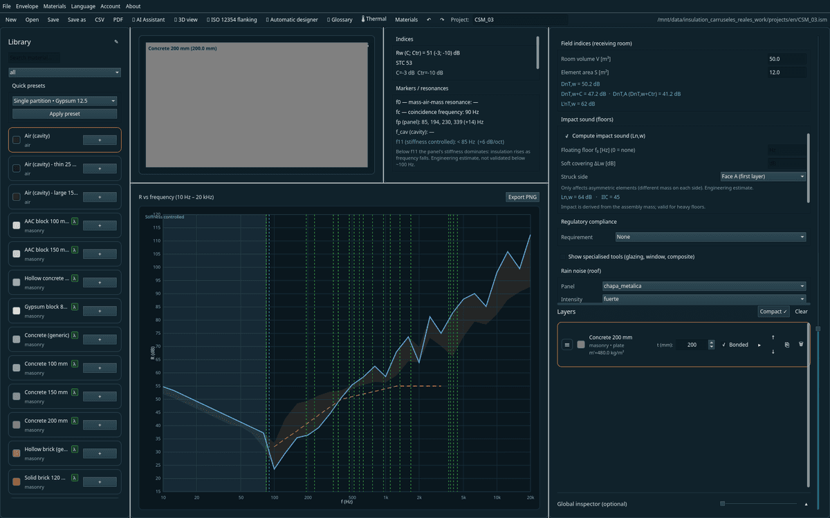
What is CSM Acoustic Insulation
A desktop application to design, compare and document the sound insulation —airborne and impact— of building assemblies. Made for acousticians, architects and firms that need to iterate quickly in the design phase and back every decision with standardized indices and demonstrated accuracy.
What sets it apart
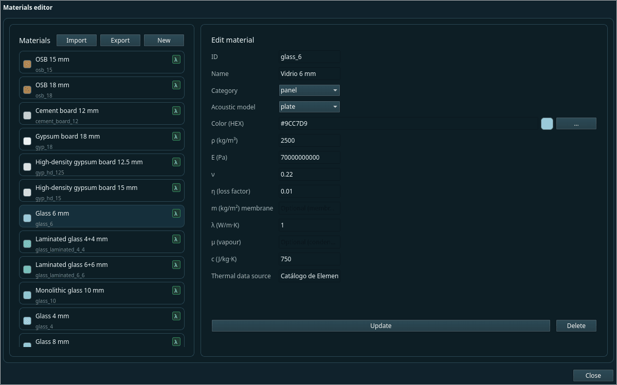
Physical data, not tabulated curves
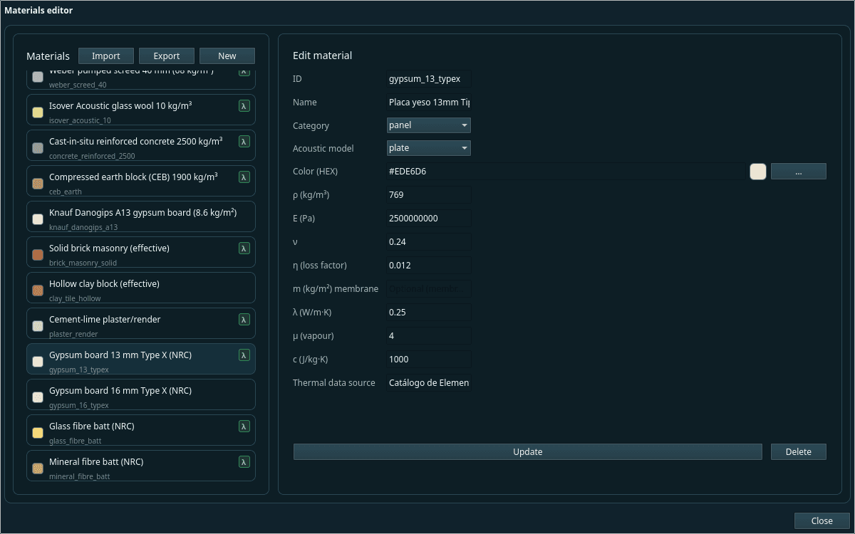
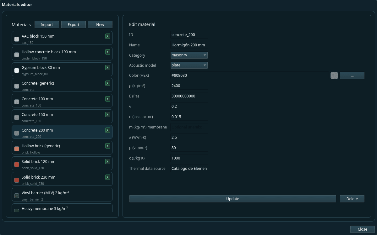
It works from density, Young's modulus and loss factor of 103 materials, not from measured curves. It computes each element's coincidence frequency instead of assuming it, and models combinations found in no table.
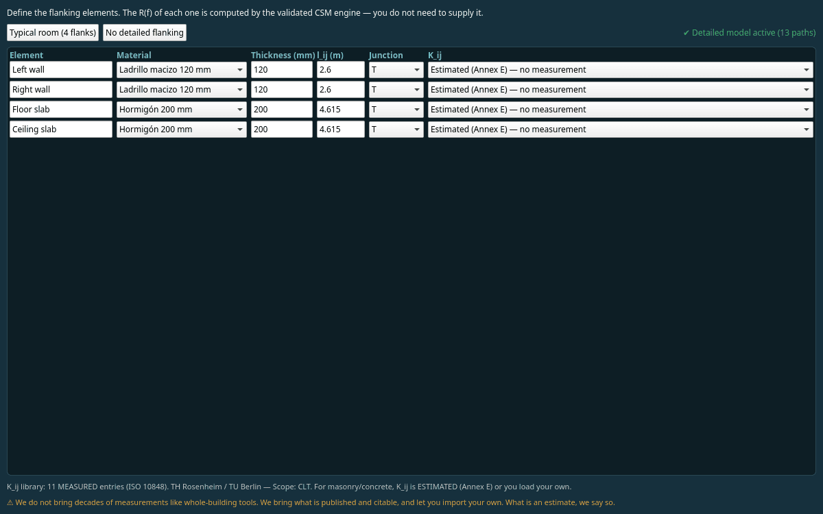
Flanking, where insulation is lost
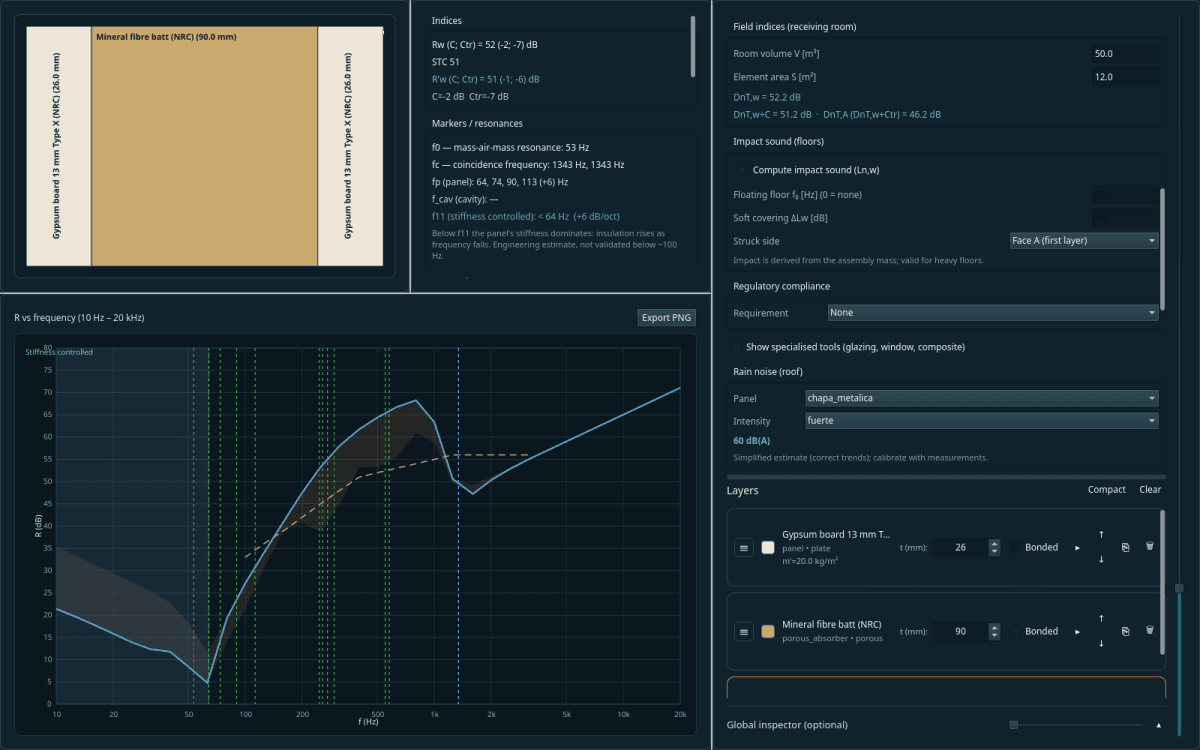
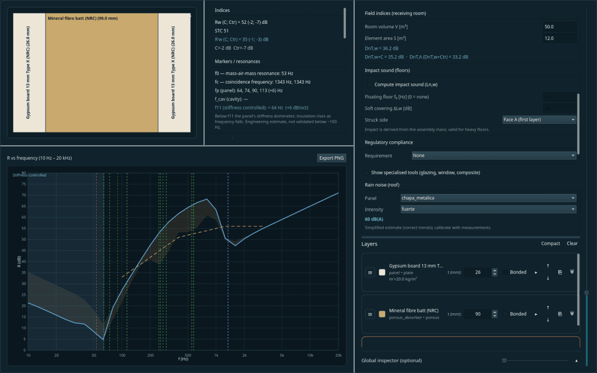
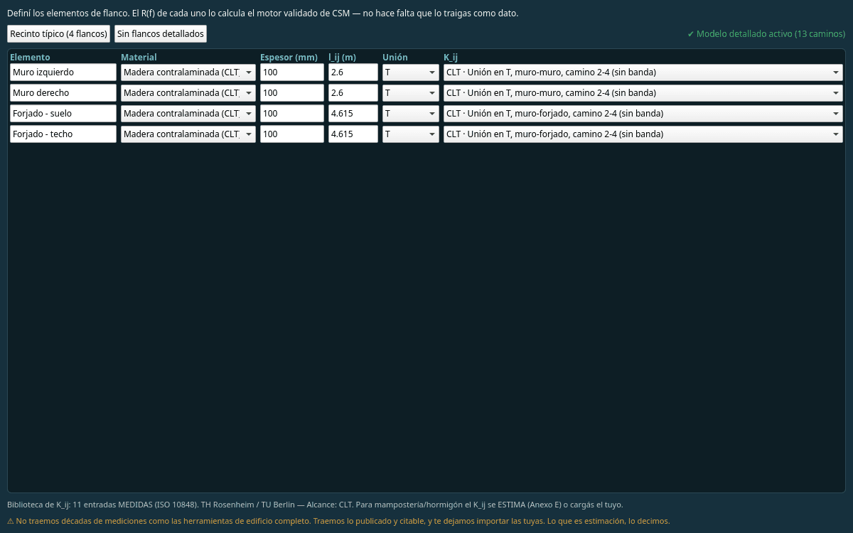
A 55 dB partition does not give 55 dB once installed: sound goes around it through the floor, the side walls and the continuous ceiling. It computes flanking transmission (ISO 12354-1) with the 13 paths of each junction, on the project's real geometry.
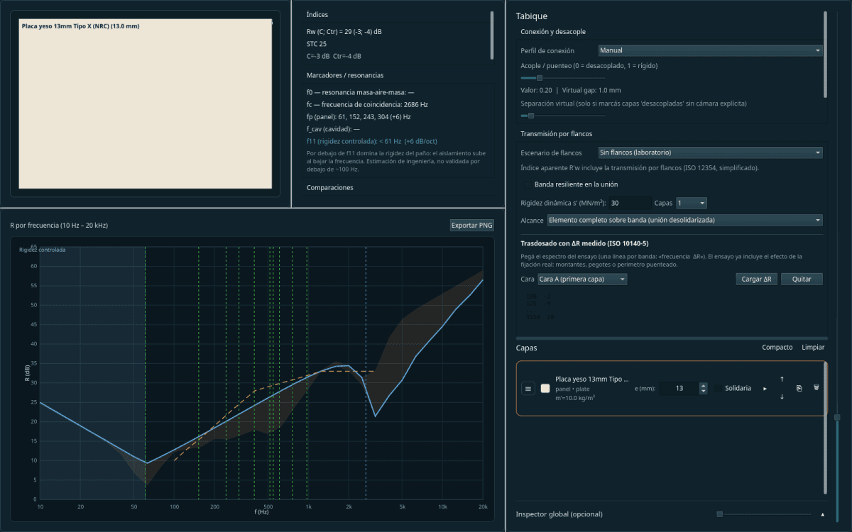
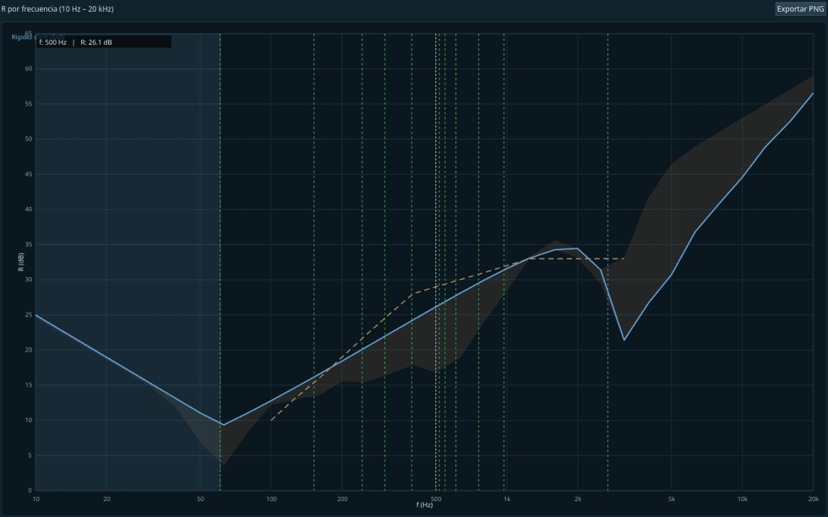
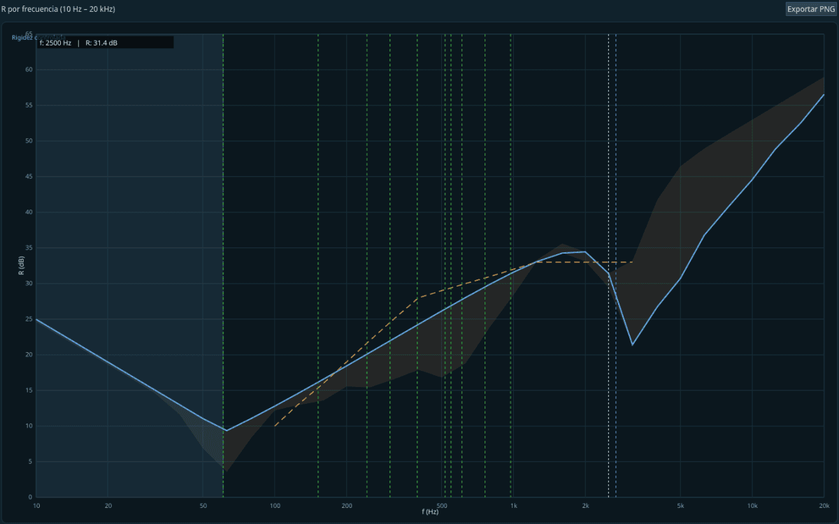
The three regions of insulation
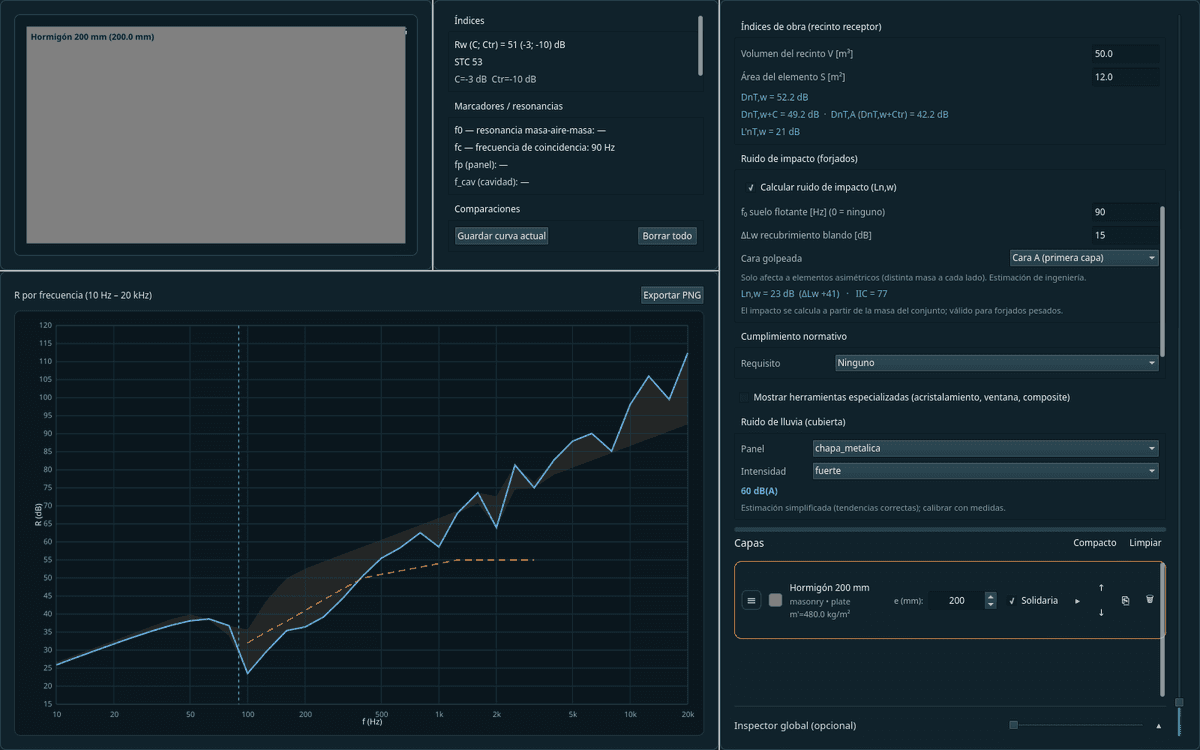
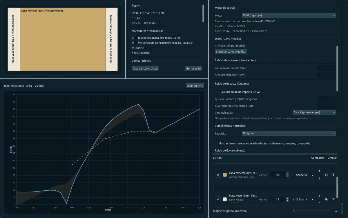
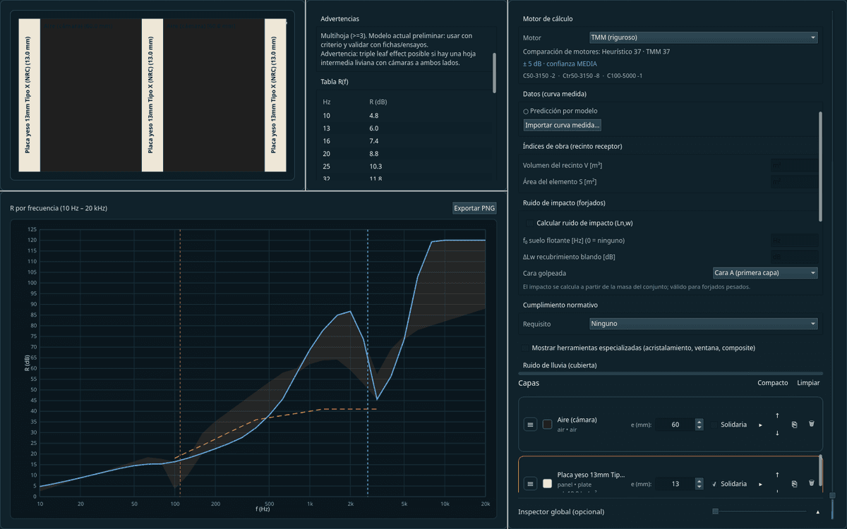
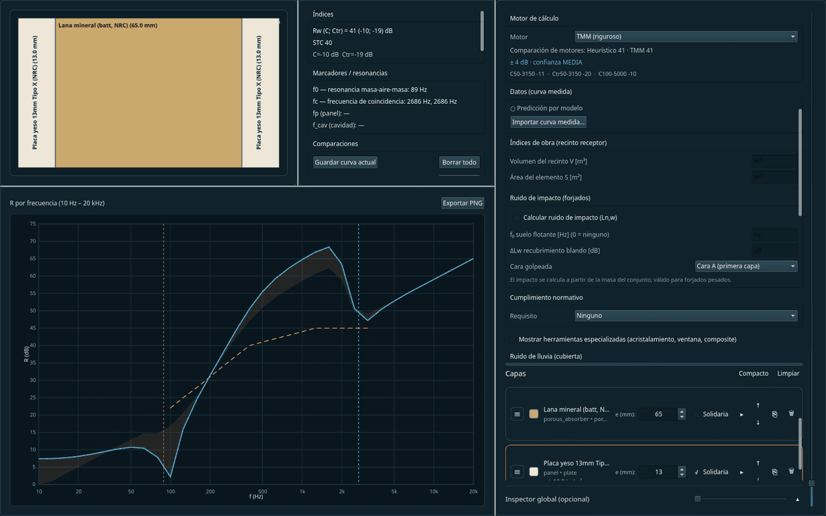
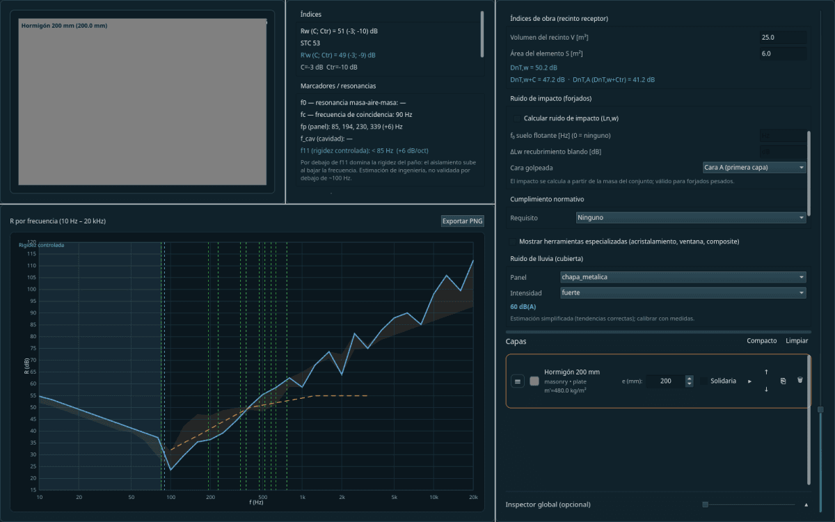
The one-third-octave R(f) curve shows the three regions that govern insulation: stiffness-controlled at low frequencies, mass law in the mids, and coincidence, where the element turns transparent because the bending wave matches the airborne one.
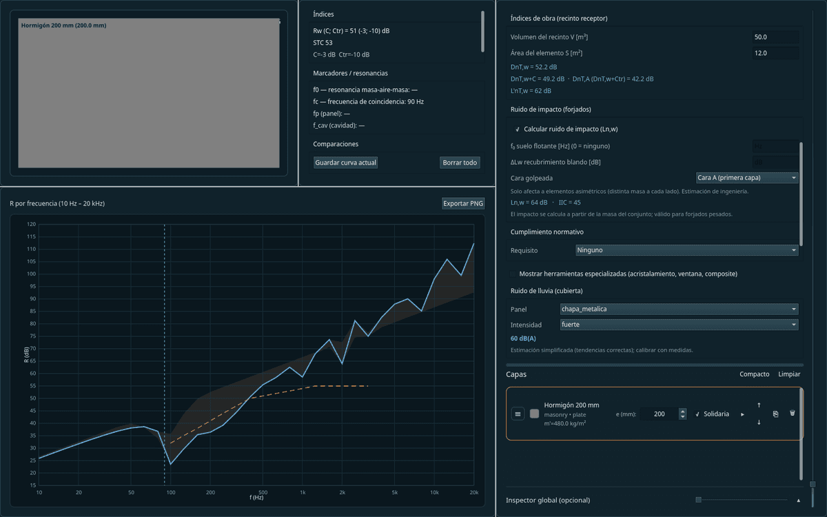
Two impact models, and it states which
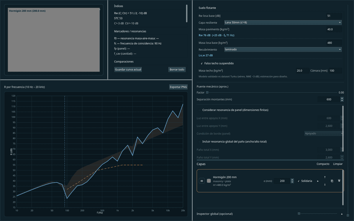
A timber joist floor is not a solid slab with an error: it transmits impact through structural vibration, not mass. The software uses the model that fits each structure and declares which one it applied, instead of forcing a single one.
Uncertainty calibrated with data
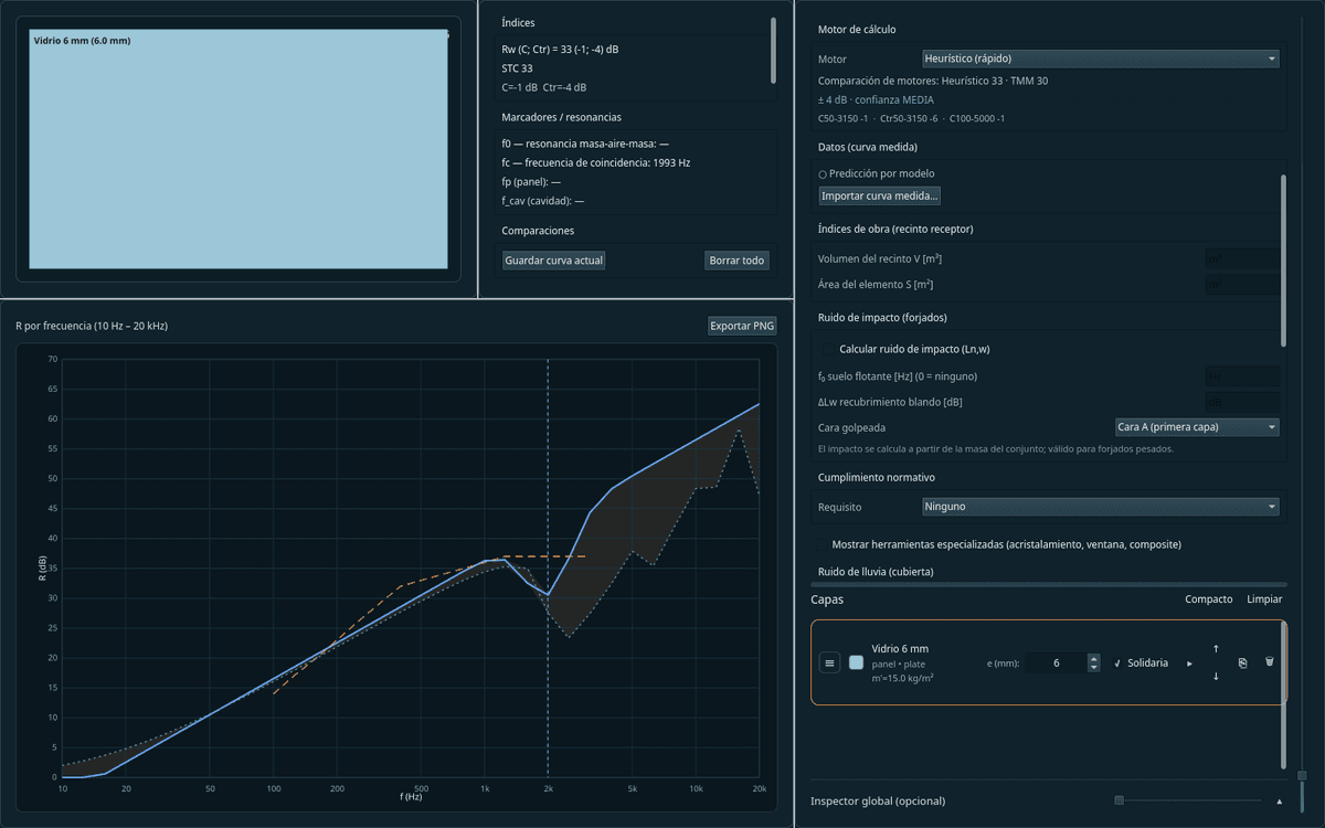
Each prediction comes with a ± band that is the measured error of that construction family, not an office estimate. And when there are few cases and the engine extrapolates, it says so: that note is the honest sign that verification is warranted there.
Each junction states its backing
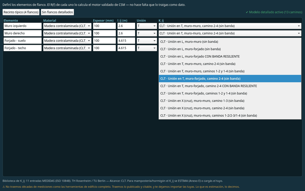
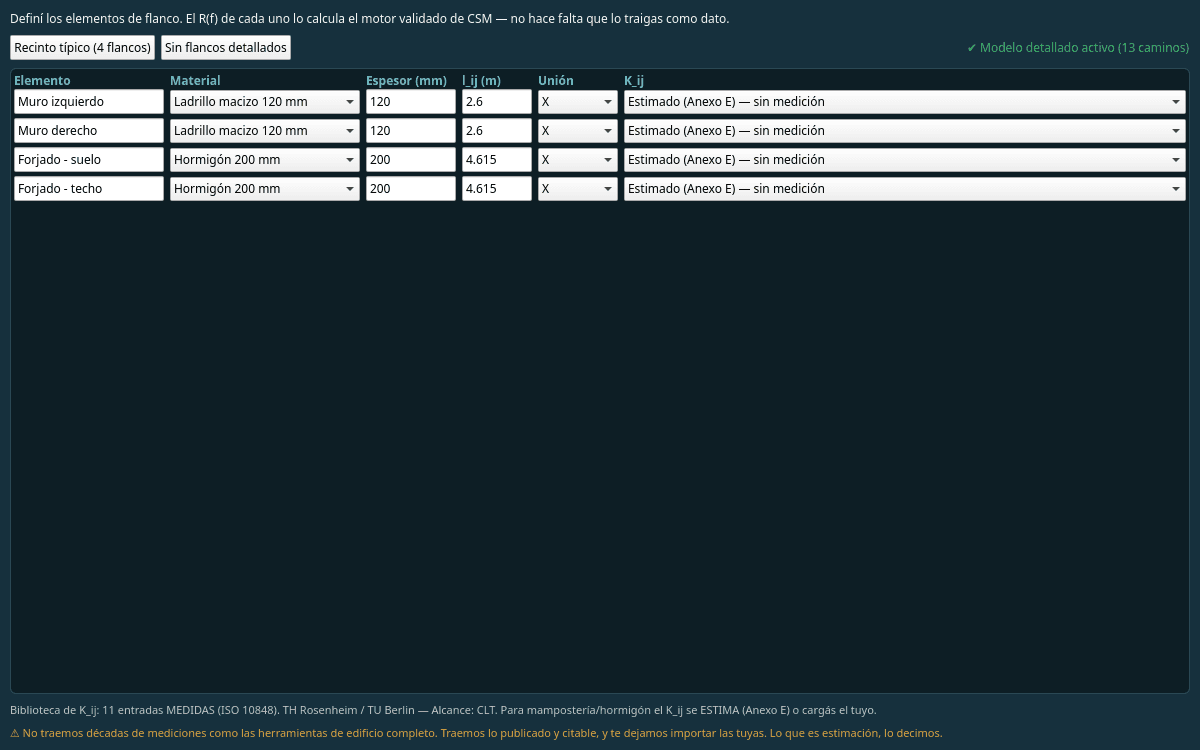
Not every junction has the same evidence behind it. The software marks each one —measured, physically verified, calibrated or order-of-magnitude— next to the result, instead of presenting them all with the same authority.
Open, auditable validation
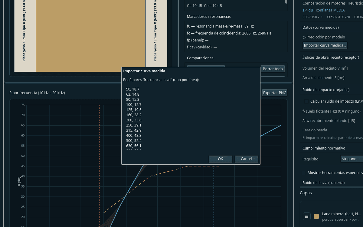
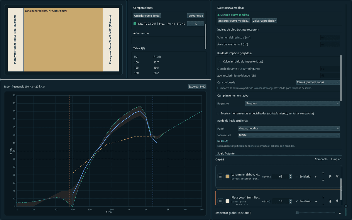
Accuracy is compared against measurements from independent accredited laboratories —not against other programs' predictions— and that verification is published in an auditable way, construction by construction.
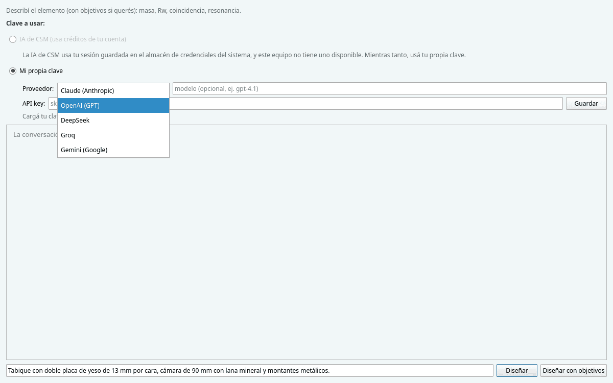
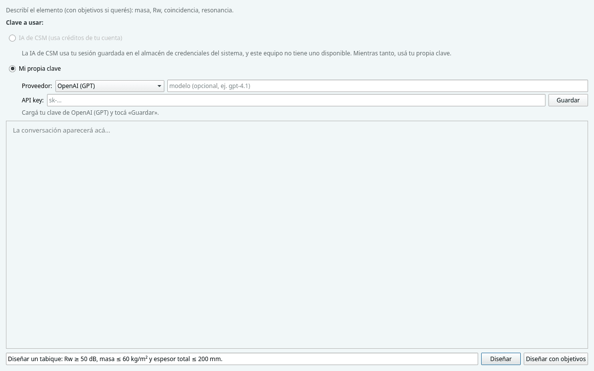
AI-assisted design
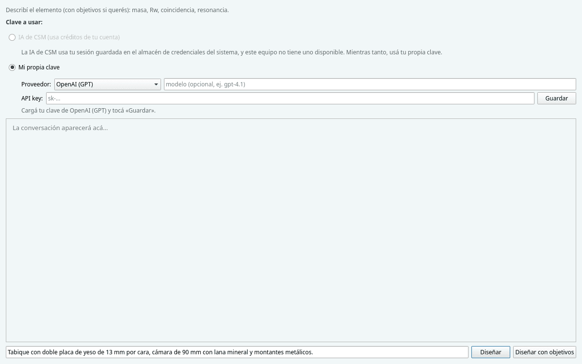
Describe the assembly in natural language and the assistant builds it, or compose the layers by hand. What the AI proposes is checked by the engine: the result comes from the calculation, not an estimate.
What you can do
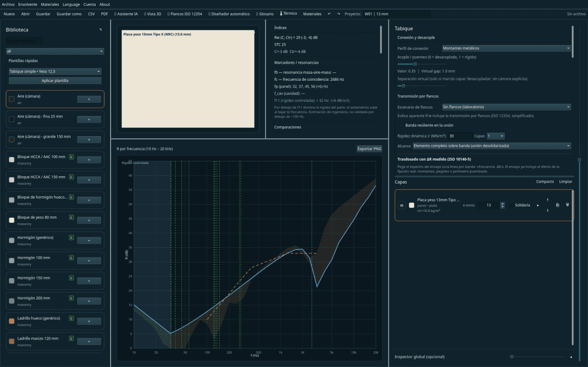
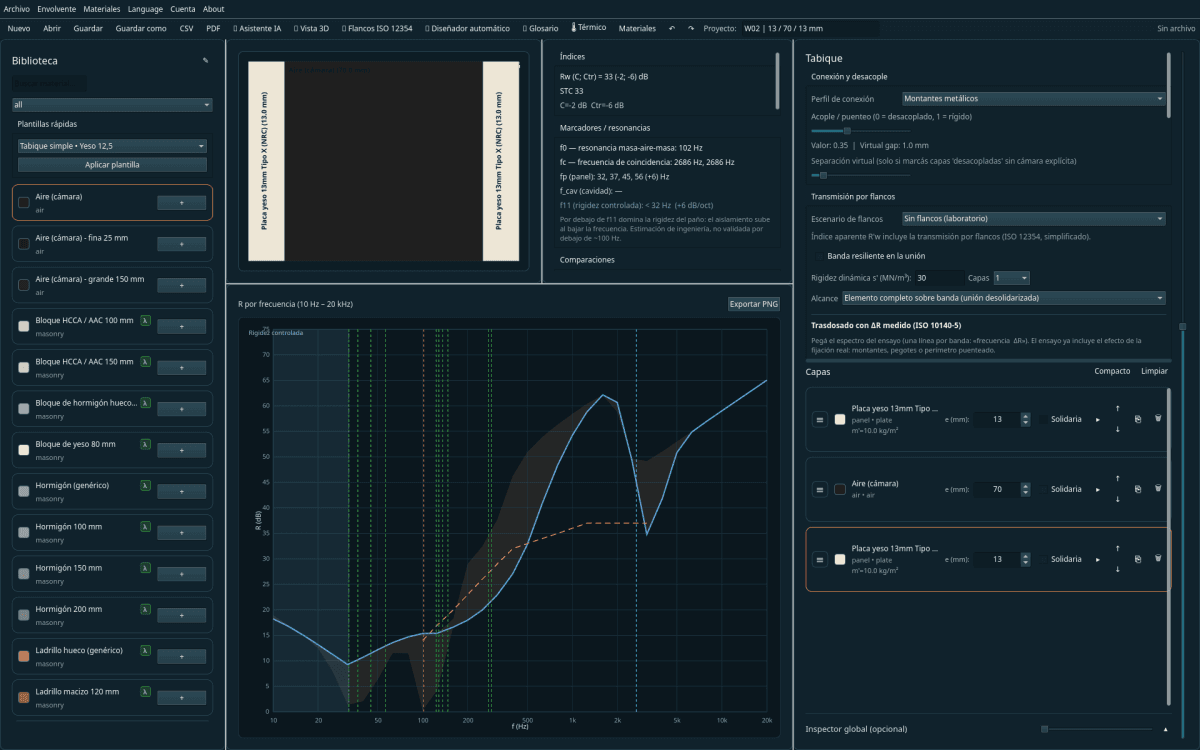
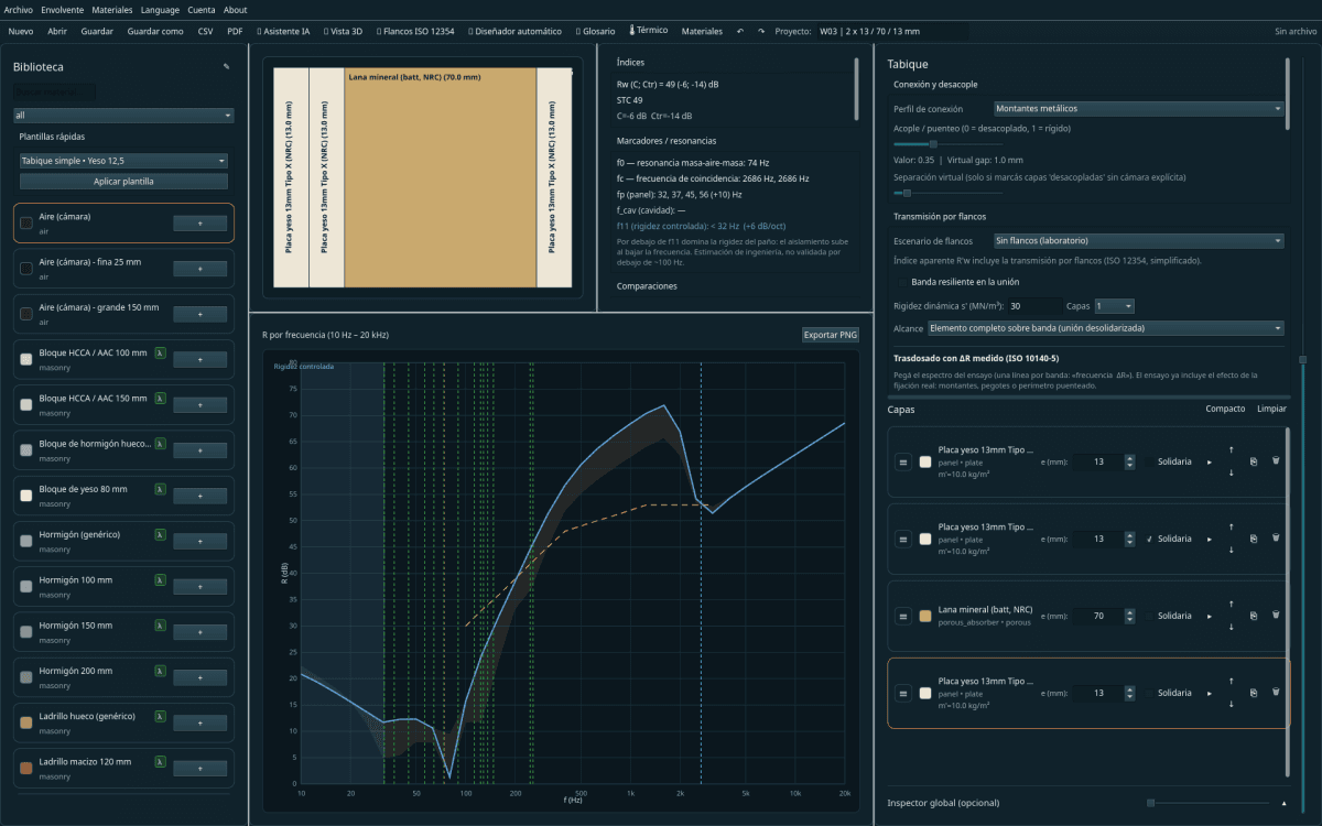
Design layer by layer
Compose the element layer by layer and watch the R(f) curve update in real time as you build it.
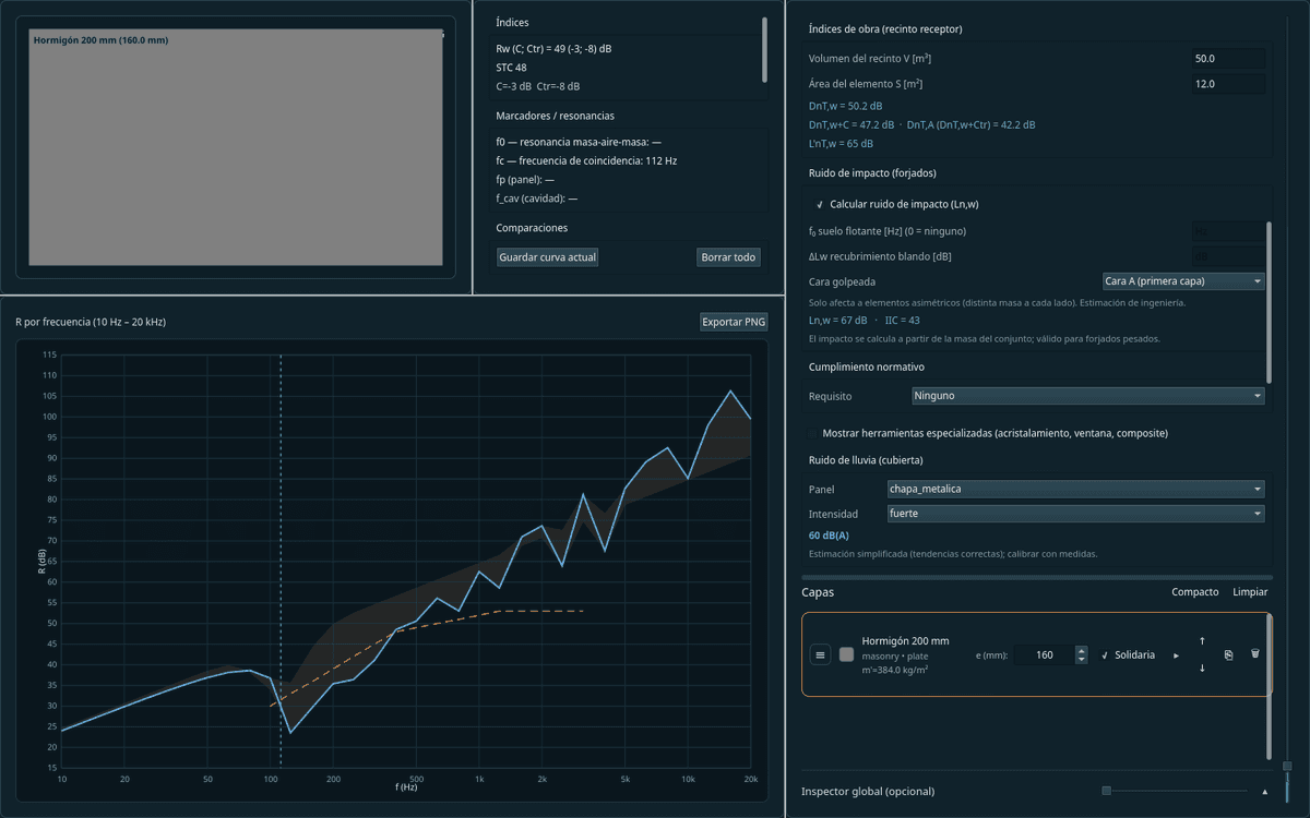
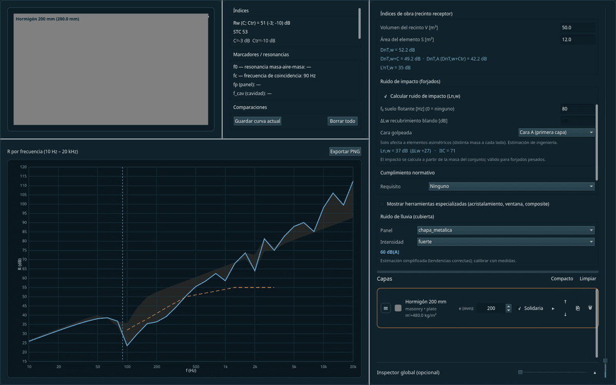
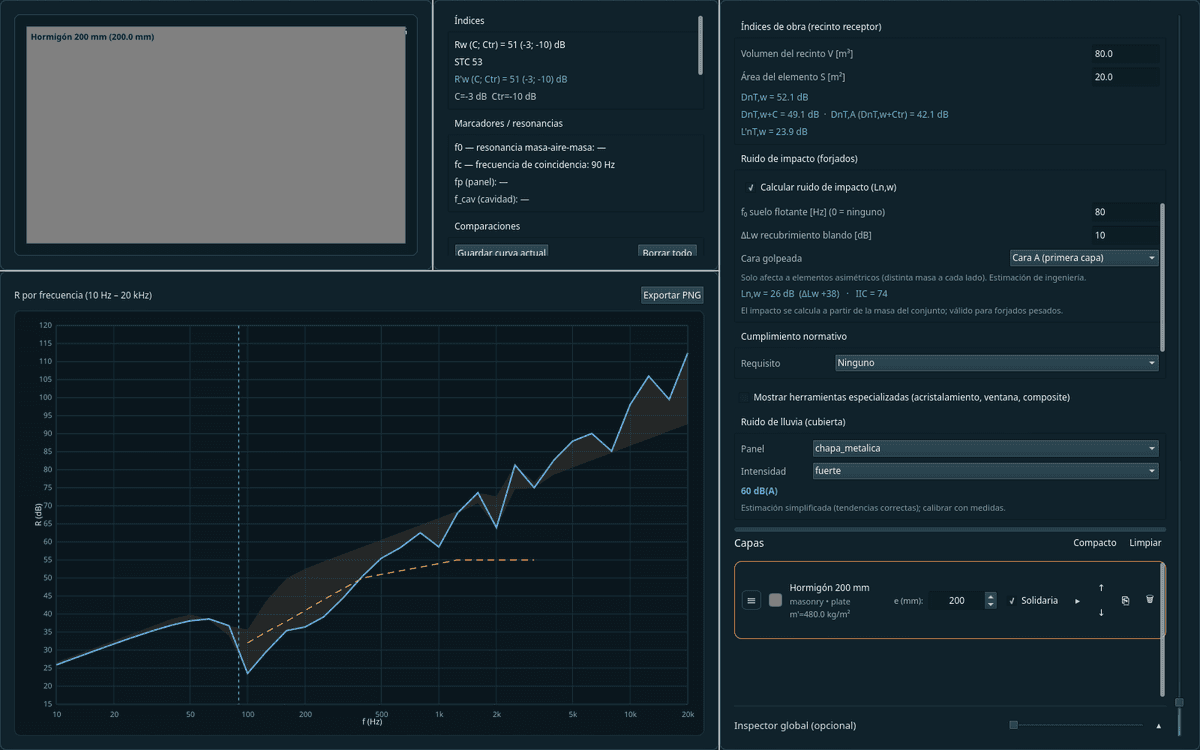
Standardized airborne and impact
Rw, C, Ctr and STC (ISO 717-1 · ASTM E413) and Ln,w (ISO 717-2) with floating floor, lining and suspended ceiling.
Solve flanking
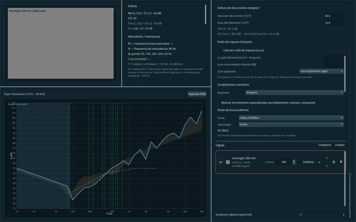
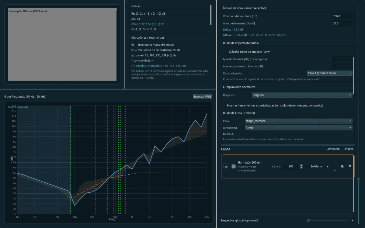
The apparent in-situ index R′w (ISO 12354-1), with each junction's four paths on the real geometry.
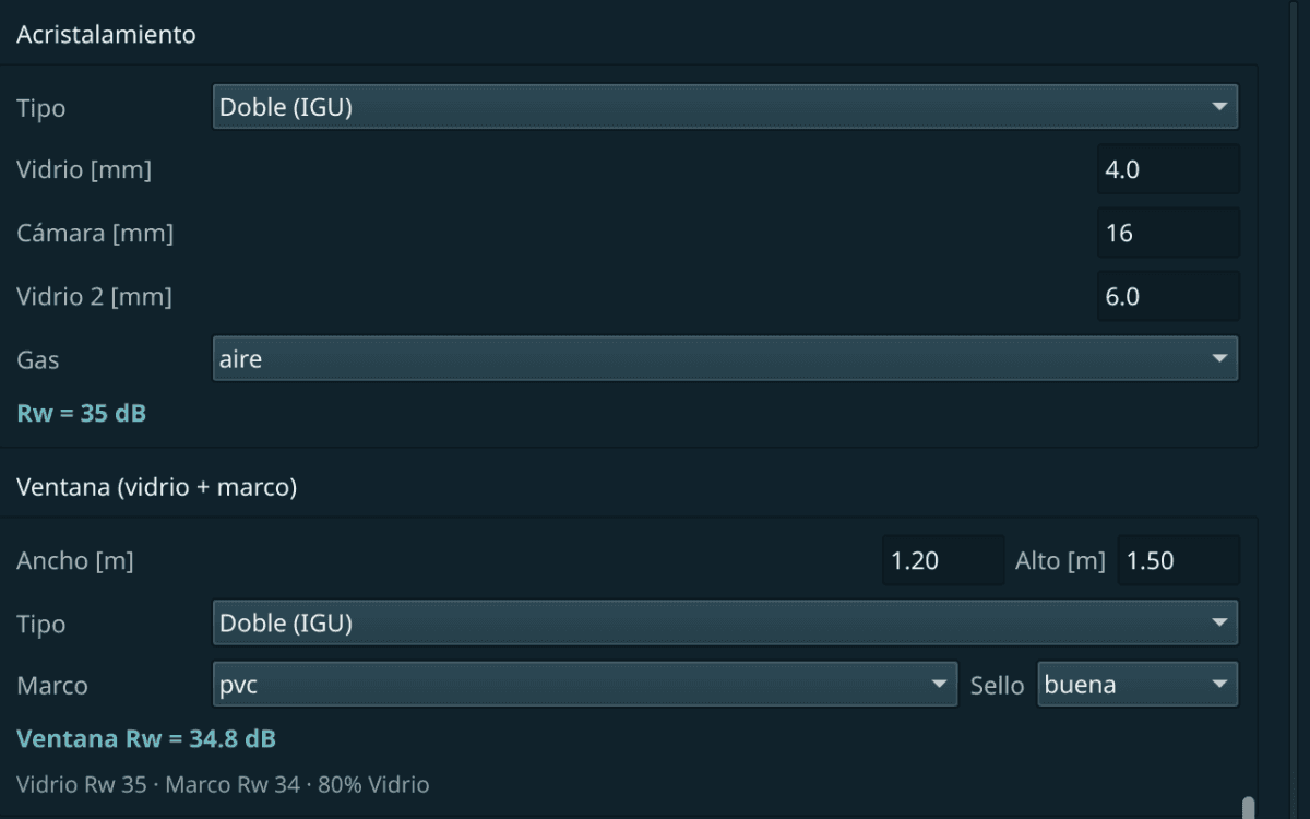
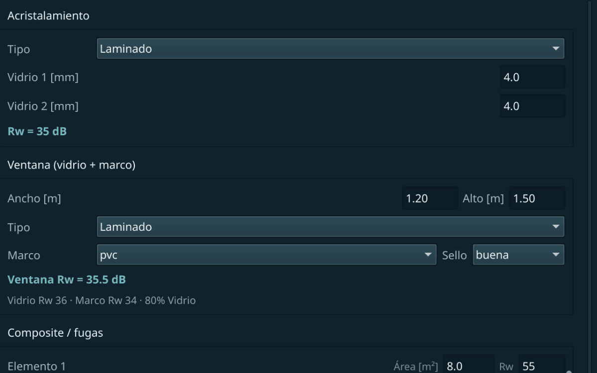
Glazing and windows
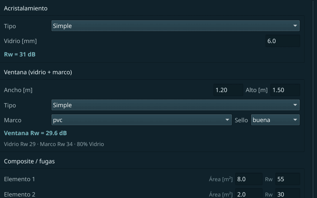
Single, double and laminated glass, with cavity and PVB — the combination the catalogue does not carry.
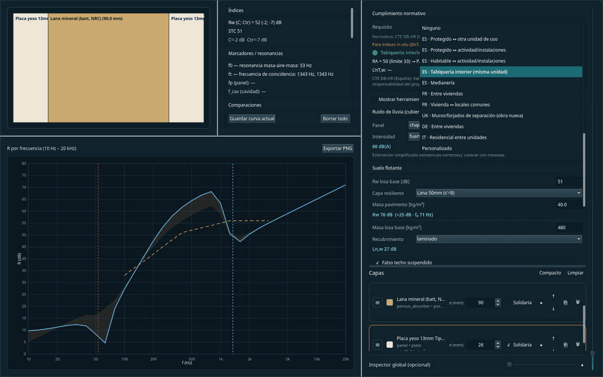
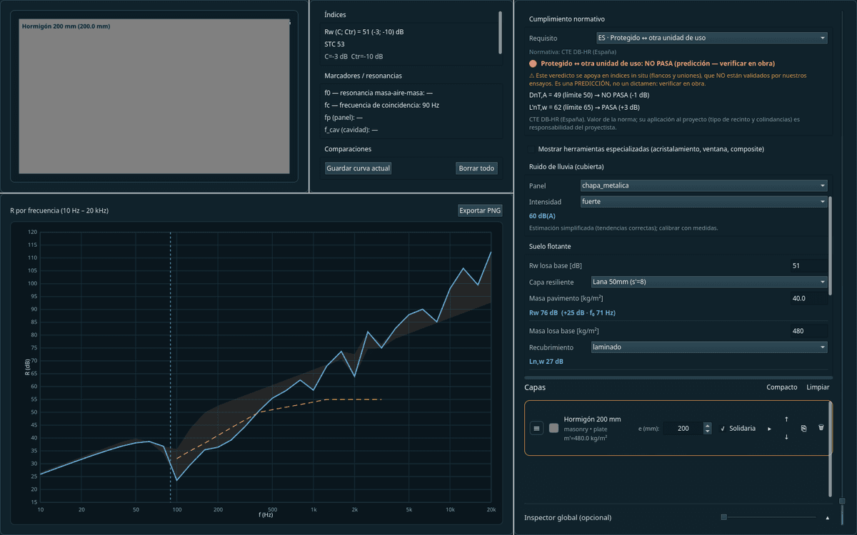
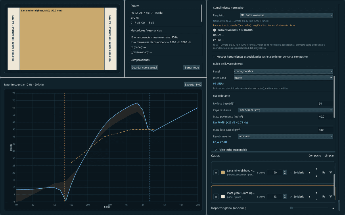
Check against the standard
Compliance against real codes (CTE DB-HR Spain, NRA France and more), with a compatibility guard.
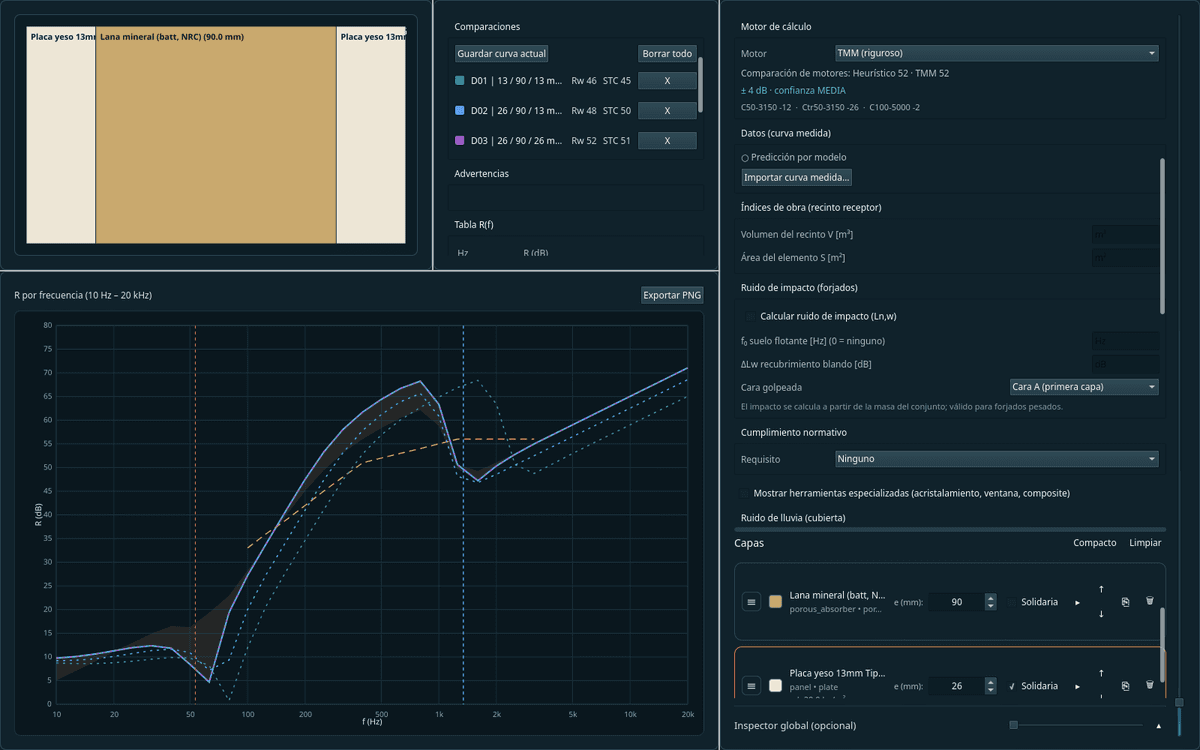
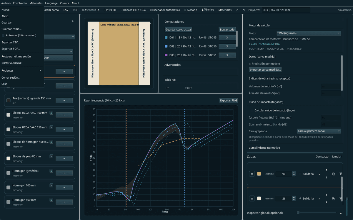
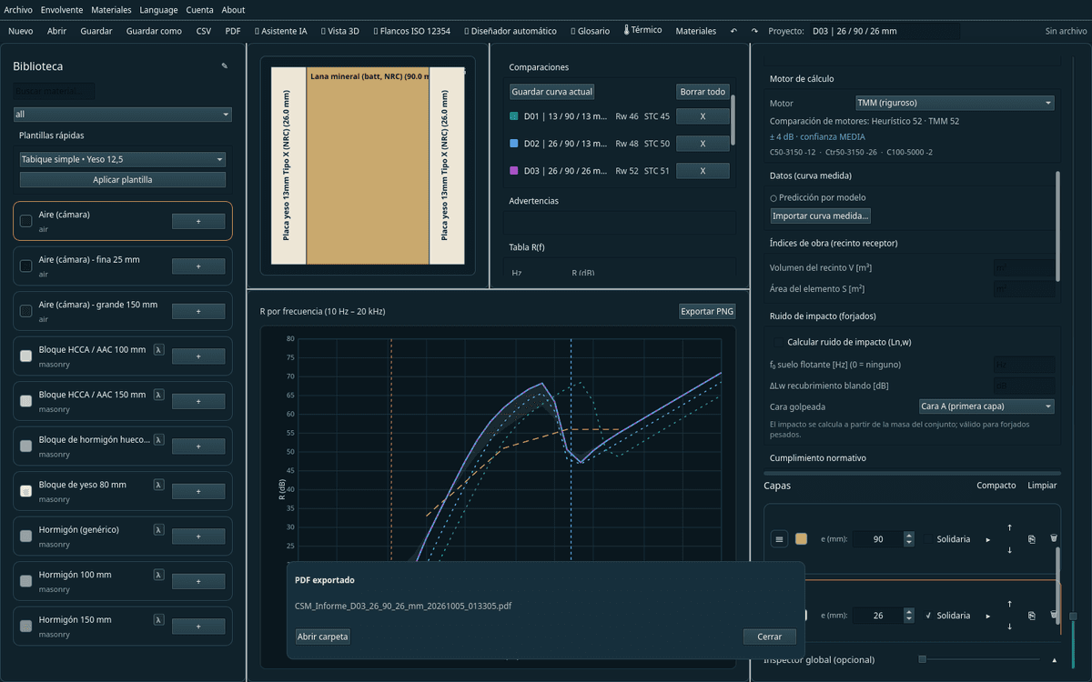
Compare and document
Several solutions on a single chart and a professional PDF report in 10 languages.
Validated, not just calculated
Accuracy is compared against public measurements from six independent accredited laboratories —NRC of Canada, Turku, Riverbank and Akustikverkstan, among others—, not against other programs' predictions, and that verification is published in an auditable way, construction by construction. The real test: on 44 walls that never tuned any parameter, STC gave a 2.82 dB mean error.
443
real constructions validated
2,29 dB
mean error in Rw (224 lab-tested, 93.8 % within ±5)
6
independent laboratories
Turku · Riverbank · NRC · EWES
Scope note
The results are engineering estimates for design and comparison of alternatives. They do not replace laboratory tests (ISO 10140) or in-situ measurements (ISO 16283).